Functionality of the robot simulation tool
Robot programs based on the packages org.jabotics.robot.en or org.jabotics.robot.de can be executed and tested within a virtual environment in the Jabotics simulation tool. Students prefer the simulation tool for small programming tasks and exercises as well as for first tests within more complex projects while using real robot hardware in the final stage of the development. The simulation tool can also be used in case of an unexpected behavior of the robot in order to rule out problems with the robot hardware. Pupils can install the development environment including the simulation tool on their own PC if they want to continue working on and testing of robot programs at home.
Starting the simulation tool
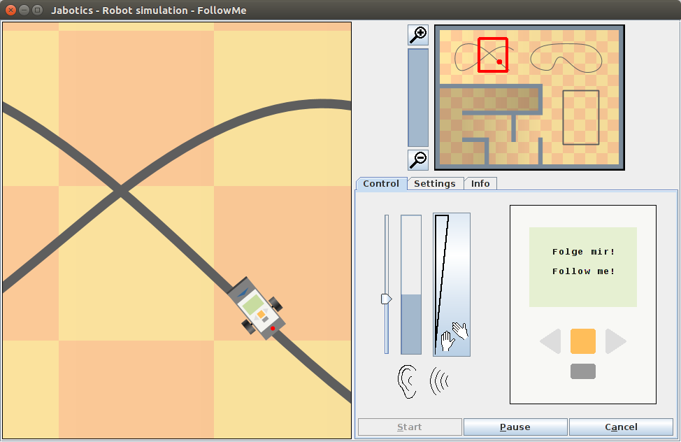
Normally the robot simulation will be started from the project view of the BlueJ IDE by means of a right-click on the robot class icon and selecting the menu item Robot → Simulate. The simulation tool will be opened with the main view on the left, an overview area at the top right and a control area at the bottom right (see the figure above). The latter area provides a control panel as shown in the figure, a settings panel (see following page) and an information panel that will display certain status messages as well as the standard and error output of the robot process. The simulation tool can also be started by a direct call to the main method of the robot class (menu item void main(String[] args) in the context menu of the class icon). For normal simulation runs this approach imposes some restrictions on the use of the simulation tool. E.g. after completing a program run it will not be possible to restart the simulation with the buttons on the control panel (compare below). On the other hand, robot programs started in this way can be examined with the debugger in BlueJ. Looking for programming errors with the debugger is not suitable for beginners, though, because the robot simulation is a multithreaded application with several concurrent threads (motor and sensor control on the robot; sound generation, graphics, and so on in the simulation tool).
Overview area
The area at the upper right displays an overall view of the simulation scenery. The red dot marks the current position of the robot and the red frame the clipping within the main view. The column to the left indicates the current zooming level (which is at its maximum value in the example above). The zooming level can be changed stepwise by clicking on the buttons with the magnifier icons.
Main view
The main view displays a detail of the scenery, automatically following the robot position. Initially the robot is located at its starting position of the previous simulation run. Before starting the execution of the robot program, the robot position can be adjusted by drag&drop. To shift the robot, move the cursor directly over the robot. The cursor will change to a shift icon. Press the left mouse button to capture the robot and move it to the desired location. To rotate the robot, move the cursor in the robot's vicinity until it changes to a rotation icon. Again, the robot needs to be captured by pressing the left mouse button before the robot can be turned to a different direction.
Apart from the robot position, the sensor settings should be checked before starting the simulation run. Again, the initial sensor settings will be taken from the previous simulation run. The sensor settings include the assignment of sensor types to the available sensor ports as well as the orientation of the sensors. The arrangement of the sensors will be displayed in the main view. In the example above, the forward-facing blue "arrow" indicates that there is an ultrasonic sensor attached to the rear of the robot in forward direction. The dot at the front of the robot represents a light sensor in downward direction, the red color indicating that the LED is currently switched on. The dark bar at the back of the robot demonstrates the position of an attached touch sensor. The following page will explain how to configure the sensor settings.
if necessary, sensor settings as well as robot position and orientation can be adjusted after the execution of the robot program has been started. Positional corrections might become necessary if the robot gets caught on a corner in the scenery. As long as the robot is captured during a drag&drop operation, the simulation will pause the execution of the robot program. For that reason, changing the robot position during a simulation run won't work if simulation breaks have been deactivated on the settings panel (see next page).
Control panel
The control panel at the bottom right contains all control elements that have to be accessible during a simulation run. In first place there is a view on the robot brick with its display and four buttons, which can be clicked on during a simulation run. To the left of the brick there are some control elements for generating a soundscape for the robot in case there is no microphone attached to the computer which could provide the input signal for the sound sensor. With the ruler, an average noise level can be preset and changed later on at any time during the simulation. Short-time pulses can be generated with the large button. The click position on the button determines the maximum sound level of the pulse (the higher the position, the louder the "clap").
With the three buttons right down at the bottom, the simulation can finally be started, paused, continued, canceled or (after completing a run) reset for a new execution.
")
")