Adjusting settings for robot simulations
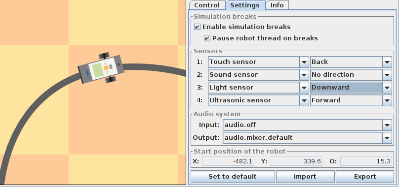
The panel Settings in the control area at the bottom right of the simulation tool combines control elements for all settings that typically have to be adjusted once prior to starting the simulation run. These settings will automatically be stored and reloaded when opening the simulation tool again. The settings can also be exported manually into an XML file and imported later on by means of the corresponding buttons at the very bottom.
Simulation breaks
The upper two check boxes control the possibility to temporarily pause simulation runs. Normally both options can and should remain checked. In case you introduce additional threads in your robot program, complications might arise that require to deactivate the second or even both options. Before introducing your own (complex) thread handling, you should check to what degree the build-in mechanisms like sensor callbacks already provide adequate solutions for your requirements. With simulation breaks being deactivated, no corrections of the robot position will be possible during a simulation run.
Sensor setttings
It is essential for a successful simulation run to carefully adjust the sensor settings. On the one hand the simulation tool will automatically detect if a wrong sensor type has been assigned to a given senor port (corresponing to positions 1 to 4 in the panel). On the other hand it will not be possible to determine the right sensor orientation since this is not visible on the program level. As a consequence, a robot program might appear to be faulty in the simulation, however the true problem is a misconfiguration. For that reason the sensor configuration is being displayed in the main view of the simulation tool. The position and orientation of ultrasonic sensors is being visualized by a blue "arrow" (in the example above: attached to the rear, forward direction). Touch sensors can be placed at the front or at the back of the robot, graphically represented by a dark bar (in the example above: one touch sensor attached to the back). Light sensors will always be attached to the front of the robot. If the sensor is mounted in downward direction, the sensor position will be marked by a gray dot (which will turn red during a simulation run once the LED is being switched on). If it is forward-facing, it will be represented by a parabolic shape instead of a dot.
Configuration of the audio system
The first combo box in the audio section allows to select the input device providing the sound background for the simulation run. If there is a built-in or connected microphone, its input signal can be forwarded to the robot's sound sensor. In the example above the audio input via microphone has been deactivated, that is, the sound control elements on the control panel have to be used to generate a soundscape for the robot (compare previous page).
The output of the robot's loudspeaker can be directed to an appropriate audio device by means of the second combo box. In the example above this is a so-called default mixer which here represents an external loudspeaker attached to the sound card. The audio mixer names to select from in the combo box appear to be somewhat cryptic for Linux systems. On Windows machines, the mixer names seem to be more comprehensible.
")
")